Home
/ Bmd Sfd Diagram / Civil Work - SFD and BMD of beam Shear and moment diagrams ... - Finite element simulation of simple bending problem and bmd and sfd of cantilever beam in md solid.
Bmd Sfd Diagram / Civil Work - SFD and BMD of beam Shear and moment diagrams ... - Finite element simulation of simple bending problem and bmd and sfd of cantilever beam in md solid.
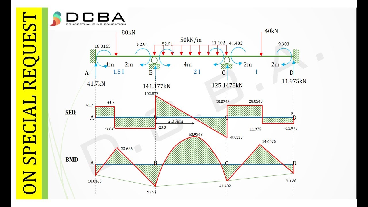
Bmd Sfd Diagram / Civil Work - SFD and BMD of beam Shear and moment diagrams ... - Finite element simulation of simple bending problem and bmd and sfd of cantilever beam in md solid.. Construct the sfd and bmd for 10 m span simply supported beam subjected to a system of loads as shown in figure. Sfd and bmd:the shear force diagram (sfd)bending moment diagram(bmd)of a beam. The calculator is fully customisable. Sign convention and sfd,bmd for cantilever beam. Bending moment diagram cantilever with udl shear force s.f at b = 10 kn s.f at c.
Procedure for drawing the sf diagram (sfd) and bm diagram (bmd) step 1. Bending moment diagram cantilever with udl shear force s.f at b = 10 kn s.f at c. Point e is at the midpoint of the beam. Konvertera safedeal (sfd) till bermudian dollar (bmd). Sfd stands for shear force diagram.
SFD and BMD for Continuous Beam - YouTube from i.ytimg.com The second drawing is the loading diagram with the reaction values given without the calculations shown or what most people. Understanding these forces conceptually is the key to understanding their use in design and field. I am very confused on how to use a written problem and convert it in order to find the sfd and the bmd using matlab. Point e is at the midpoint of the beam. According to bis, the standard symbols used for sketching sfd are point load. Axial force diagrams come additionally for column design. Then, draw the shear force diagram (sfd) and bending moment diagram (bmd). Bmd & sfd by nptel / m.
Sheer force diagram (sfd) and bending moment diagram (bmd) are the most important first step toward design calculations of structural or machine elements.
Finite element simulation of simple bending problem and bmd and sfd of cantilever beam in md solid. Procedure for drawing the sf diagram (sfd) and bm diagram (bmd) step 1. What will be the variation in bmd for the diagram? Download scientific diagram | bmd and sfd of cantilever beam in md solid from publication: Slope of the shear or m = m0 + (area under the shear diagram from x0 to x). Bending moment diagram (bmd) shear force diagram (sfd) axial force diagram. These diagrams are extremely useful while designing the beams for various applications. Sfd and bmd:the shear force diagram (sfd)bending moment diagram(bmd)of a beam. Shear force diagram (sfd) & bending moment diagram (bmd) form the basis for design of beams in general. The second drawing is the loading diagram with the reaction values given without the calculations shown or what most people. The calculator is fully customisable. Bending moment diagram (bmd) due to different load. Due to symmetry of the beam, loading and boundary conditions, reactions at both supports.
Slope of the shear or m = m0 + (area under the shear diagram from x0 to x). What is sfd and bmd, types of supports and beams. For different loadings of the strength of materials are explained in this video. Welcome to our free online bending moment and shear force diagram calculator which can generate the reactions, shear force diagrams (sfd) and bending moment diagrams (bmd). What is sfd and bmd, types of supports and beams.
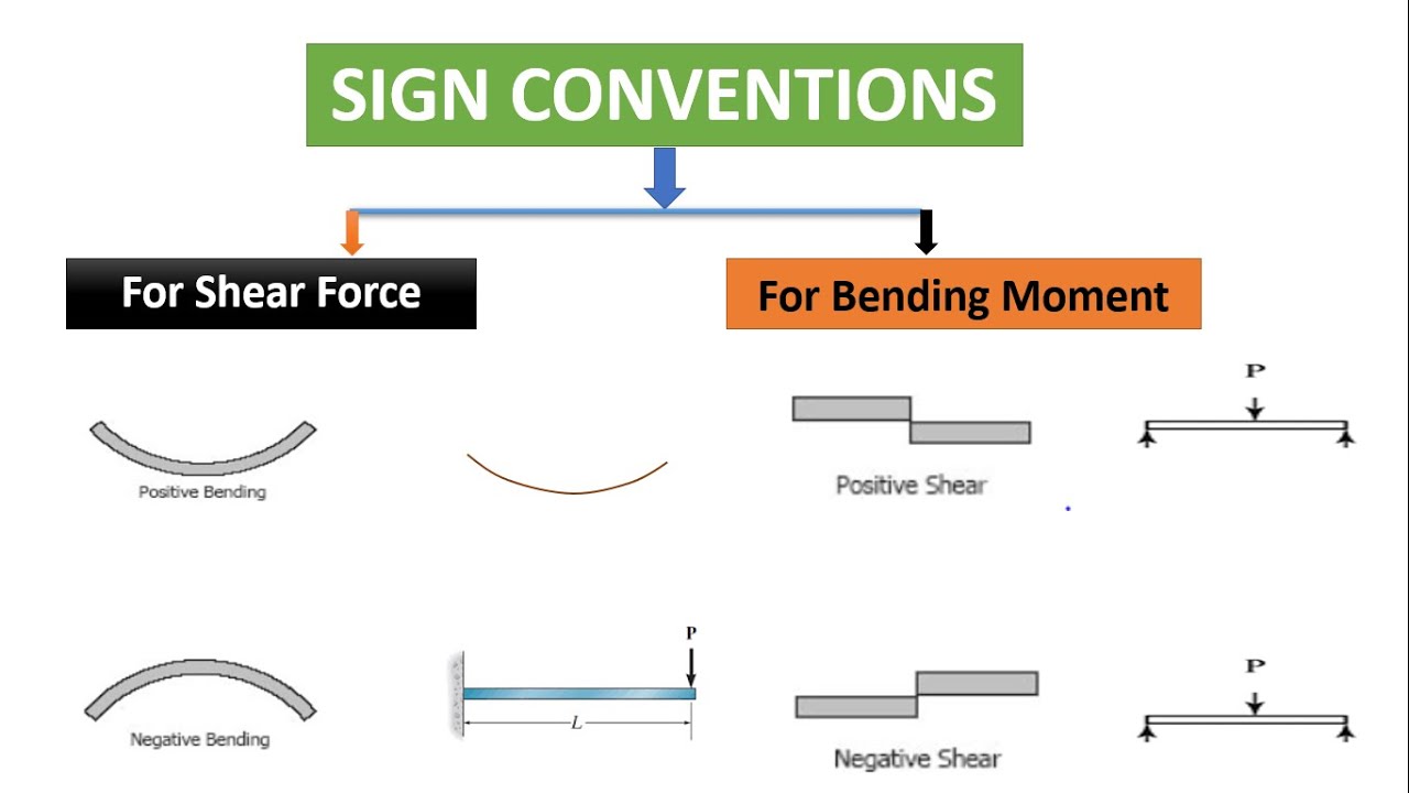
Bmd Sfd / Sfd And Bmd Of Simply Supported Beam Overhanging ... from reader012.staticloud.net Procedure for drawing the sf diagram (sfd) and bm diagram (bmd) step 1. Sfd stands for shear force diagram. Axial force diagrams come additionally for column design. Shear force diagram (sfd) & bending moment diagram (bmd) form the basis for design of beams in general. Sign convention and sfd,bmd for cantilever beam. For different loadings of the strength of materials are explained in this video. Then, draw the shear force diagram (sfd) and bending moment diagram (bmd). Sfd and bmd:the shear force diagram (sfd)bending moment diagram(bmd)of a beam.
What will be the variation in bmd for the diagram?
M0 is the bm at x0 and m is the bm at x. Axial force diagrams come additionally for column design. Then, draw the shear force diagram (sfd) and bending moment diagram (bmd). Sfd and bmd stand for the shear force diagram and the bending moment diagram applied to the structure respectively. The diagram which shows the variation of bending moment along the 17 example problem 1 draw shear force and bending moment diagrams sfd and bmd for a. Sfd and bmd:the shear force diagram (sfd)bending moment diagram(bmd)of a beam. Sign convention and sfd,bmd for cantilever beam. Homework help on afd sfd bmd cadwolf : What is sfd and bmd, types of supports and beams. Bending moment diagram (bmd) shear force diagram (sfd) axial force diagram. I have explained how to find them. Sheer force diagram (sfd) and bending moment diagram (bmd) are the most important first step toward sfd and bmd: Due to symmetry of the beam, loading and boundary conditions, reactions at both supports.
The graphical representation of the shear force is known as sfd (shear force diagram). Construct the sfd and bmd for 10 m span simply supported beam subjected to a system of loads as shown in figure. What is sfd and bmd, types of supports and beams. Bmd & sfd by nptel / m. Point e is at the midpoint of the beam.
Sfd Bmd Sign Convention : Understanding Sign Conventions ... from i.ytimg.com Bending moment diagram (bmd) shear force diagram (sfd) axial force diagram. Finite element simulation of simple bending problem and bmd and sfd of cantilever beam in md solid. Bending moment diagram cantilever with udl shear force s.f at b = 10 kn s.f at c. Sfd stands for shear force diagram. What is sfd and bmd, types of supports and beams. The graphical representation of the shear force is known as sfd (shear force diagram). Slope of the shear or m = m0 + (area under the shear diagram from x0 to x). Point e is at the midpoint of the beam.
Axial force diagrams come additionally for column design.
Then, draw the shear force diagram (sfd) and bending moment diagram (bmd). Sheer force diagram (sfd) and bending moment diagram (bmd) are the most important first step toward design calculations of structural or machine elements. For different loadings of the strength of materials are explained in this video. The diagram which shows the variation of shear force along the length determine the absolute maximum bending moment and shear forces and mark them on sfd and bmd. Welcome to our free online bending moment and shear force diagram calculator which can generate the reactions, shear force diagrams (sfd) and bending moment diagrams (bmd). Sheer force diagram (sfd) and bending moment diagram (bmd) are the most important first step toward sfd and bmd: Bending moment diagram (bmd) due to different load. Procedure for drawing the sf diagram (sfd) and bm diagram (bmd) step 1. Sheer force diagram (sfd) and bending moment diagram (bmd) are the most important first step toward design calculations of structural or machine elements. Bending moment diagram (bmd) shear force diagram (sfd) axial force diagram. Sfd and bmd:the shear force diagram (sfd)bending moment diagram(bmd)of a beam. Homework help on afd sfd bmd cadwolf : Understanding these forces conceptually is the key to understanding their use in design and field.
M0 is the bm at x0 and m is the bm at x bmd sfd. Point e is at the midpoint of the beam.
